Overview
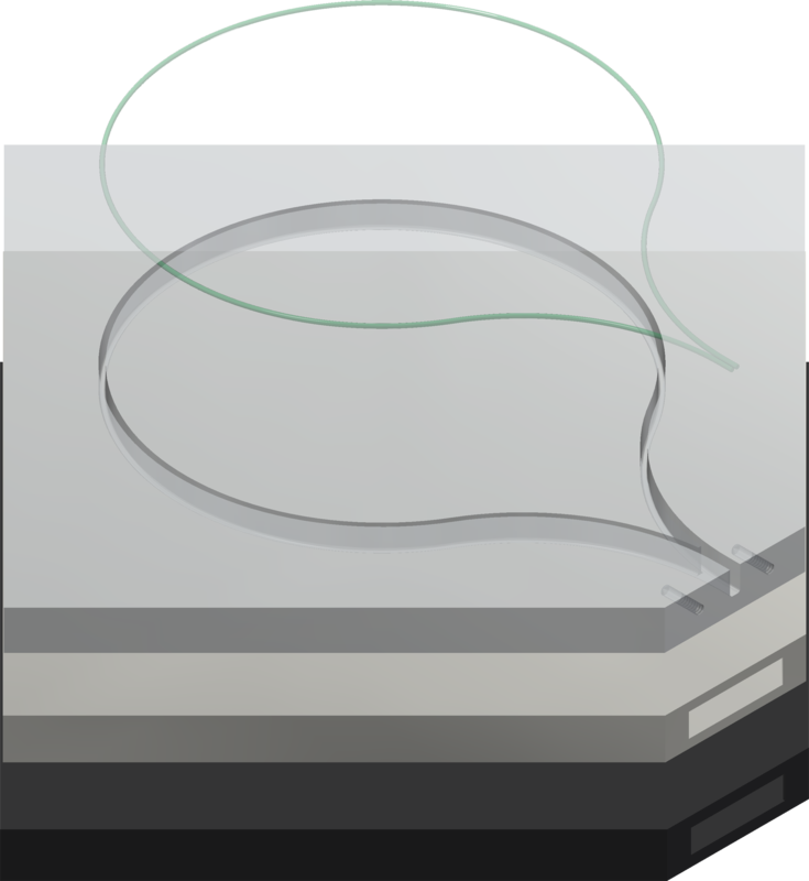
The scintillator panel is a doped plastic that emits light in response to being struck by an electron, alpha particle,
ion, or high energy photon. The light emitted is then reflected until it hits the embedded fibre that can absorb that
light, and retransmit at the lower green frequency. This green light is captured and guided by the fibre to the end of
the panel where it can be read out. Each event is expected to produce about 30 photons, with a lower number reaching the
sensor placed on the fibre side.
Mechanism of Action
The scintillator is made up of a base plastic such as Polyvinyl toluene (PVT) or Polystyrene (PS). The plastic can
fluoresce when a charged particle interacts and deposits energy into the material.
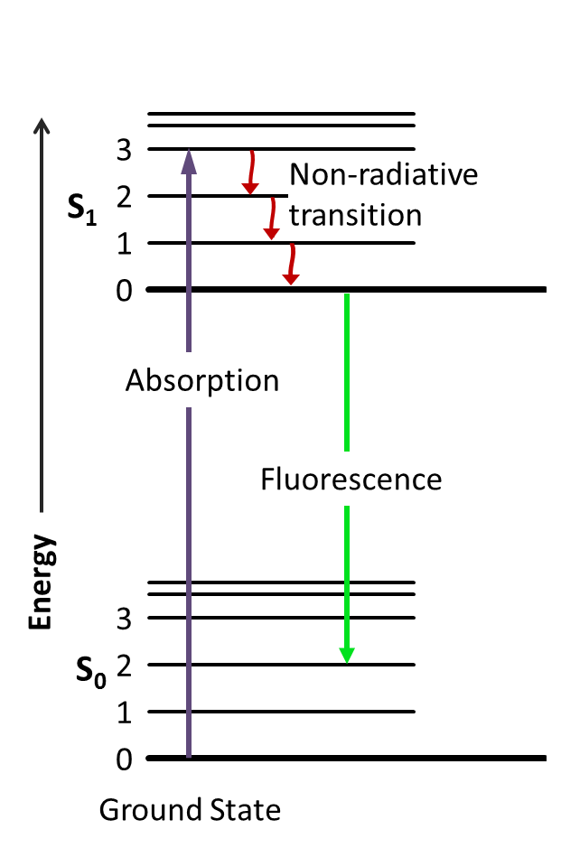
This effect is based on the valance electrons of the molecule, manifests best in aromatic systems, ideally benzene rings and the analysis can
get rather involved. The incoming charged particle travels though the material and interacts with the valance electrons
either though the coulomb force or directly at a vibrational level and excite the valance electron to a higher energy
level. Based on the stability of the excited state, generally very low, the electron travels through a decay chain in
around 10ps to 1us and based on the electronic states and the transitions in between determined though the chemical
makeup. The output photons are generally in the ultraviolet region. This example is given with electron states, but the
physics occurs with the entire molecule and using primarily vibrational and rotational states.
The light generated is quite small and opaque to the scintillation medium so a dopant, known as a "flor", for
luminophors, also referred to a secondary scintillator is added. These compounds absorb the photons generated from the
base scintillation mechanism, and re-emit them at a lower frequency, shifting the light into a wavelength that the base
is more transparent to. Even after all this we get approximately fifty photons per particle though 1cm of our
scintillator.
Parameters
The composition percentages and closely guarded secrets by the manufacturers but are tuned to different uses. Some of
the important parameters are the following, and should be avalible in the datasheet.
Optical attenuation length
The distance where the intensity of the light has dropped to 1/e or around 63%.
Timing
The rise and fall time of the light pulse. The decay chain of the electrons in between the energy levels are based on
probability and there is some timing variation. A fast rise time is useful for timing measurements and a short decay
time provides a lower dead time between readings. This refers to the final light output, so it includes the interaction
of the primary and secondary scintillation material.
Emission Frequency
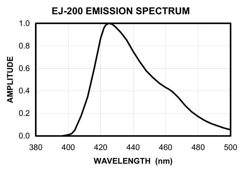 Unlike what we would expect from a single band emission, the emission is a spectrum. This is caused by there being many
vibrational and for each multiple rotational band. This yields an output where the individual bands are so numerous it
is not possible to resolve each transition and the output is a spectrum.
Unlike what we would expect from a single band emission, the emission is a spectrum. This is caused by there being many
vibrational and for each multiple rotational band. This yields an output where the individual bands are so numerous it
is not possible to resolve each transition and the output is a spectrum.
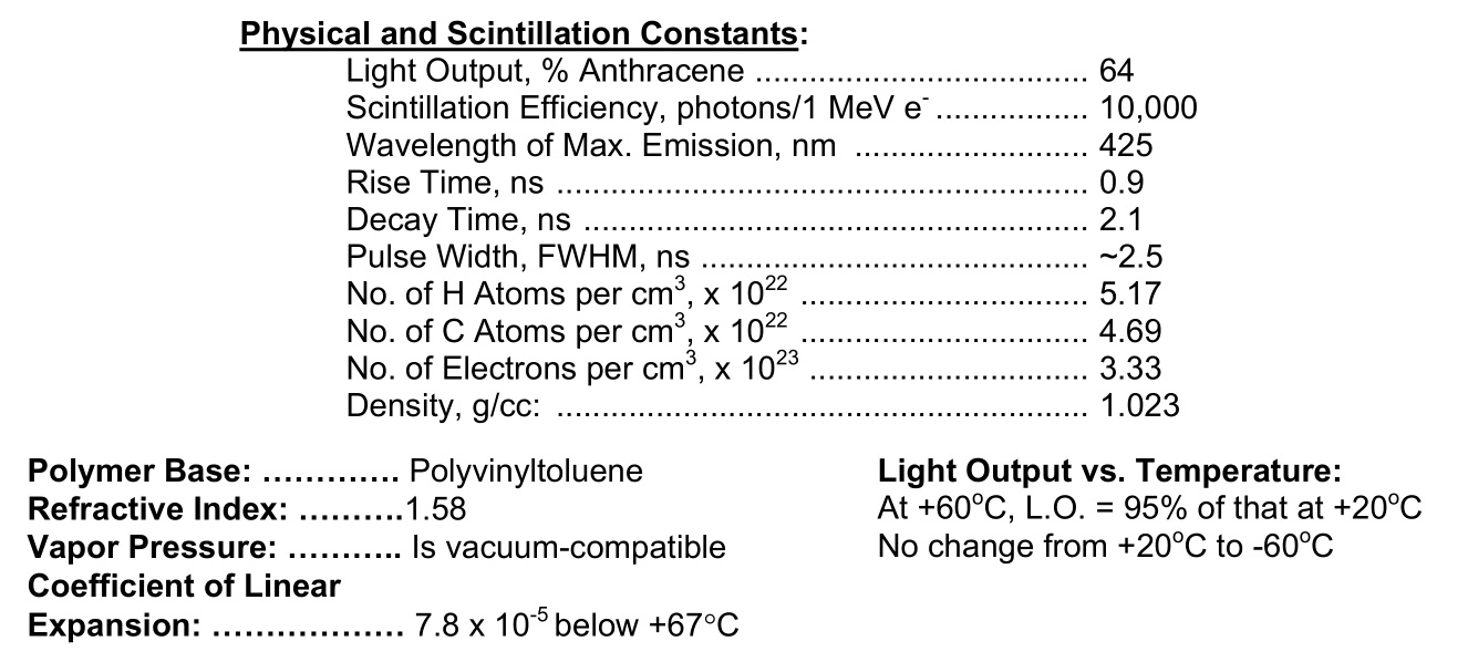
Output efficiency
The efficiency of the material to convert energy absorbed from the particle into light. It can be measured in photons/1
MeV e- or as a percentage of anthracene. Anthracene is an organic scintillator with the highest light output and is used
as a reference.
Sources
[Datasheet/Catalogs printouts]
There are multiple manufacturers of plastic scintillators available, for our first generation we used Eljen EJ-200 and
are looking into other manufacturers for future iterations that can automate more of the further processes. Eljen is
better known in the US and Saint-Gobain is more popular in Europe.
Fiber
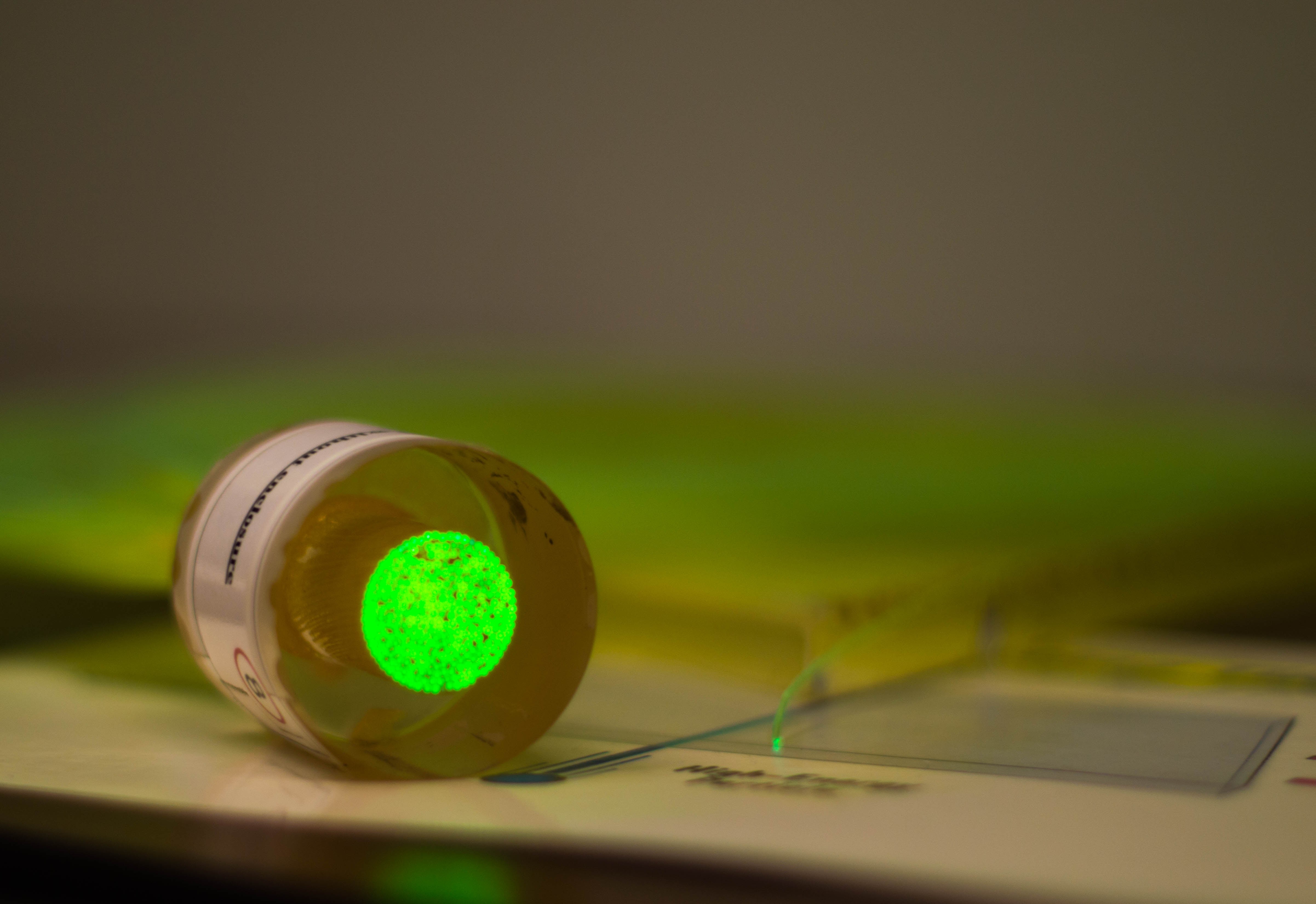 Wavelength shifting fibers are plastic scintillators material formed into fibers and have a cladding similar to fiber
optic for light trapping and guiding.
[Kuraray Y-11 Datasheet]
Kuraray Y-11 is a 1mm blue to green wavelength shifting fiber and has a polystyrene core and a PMAA
(Polymethylmethacrylate) cladding of a single layer.
Wavelength shifting fibers are plastic scintillators material formed into fibers and have a cladding similar to fiber
optic for light trapping and guiding.
[Kuraray Y-11 Datasheet]
Kuraray Y-11 is a 1mm blue to green wavelength shifting fiber and has a polystyrene core and a PMAA
(Polymethylmethacrylate) cladding of a single layer.
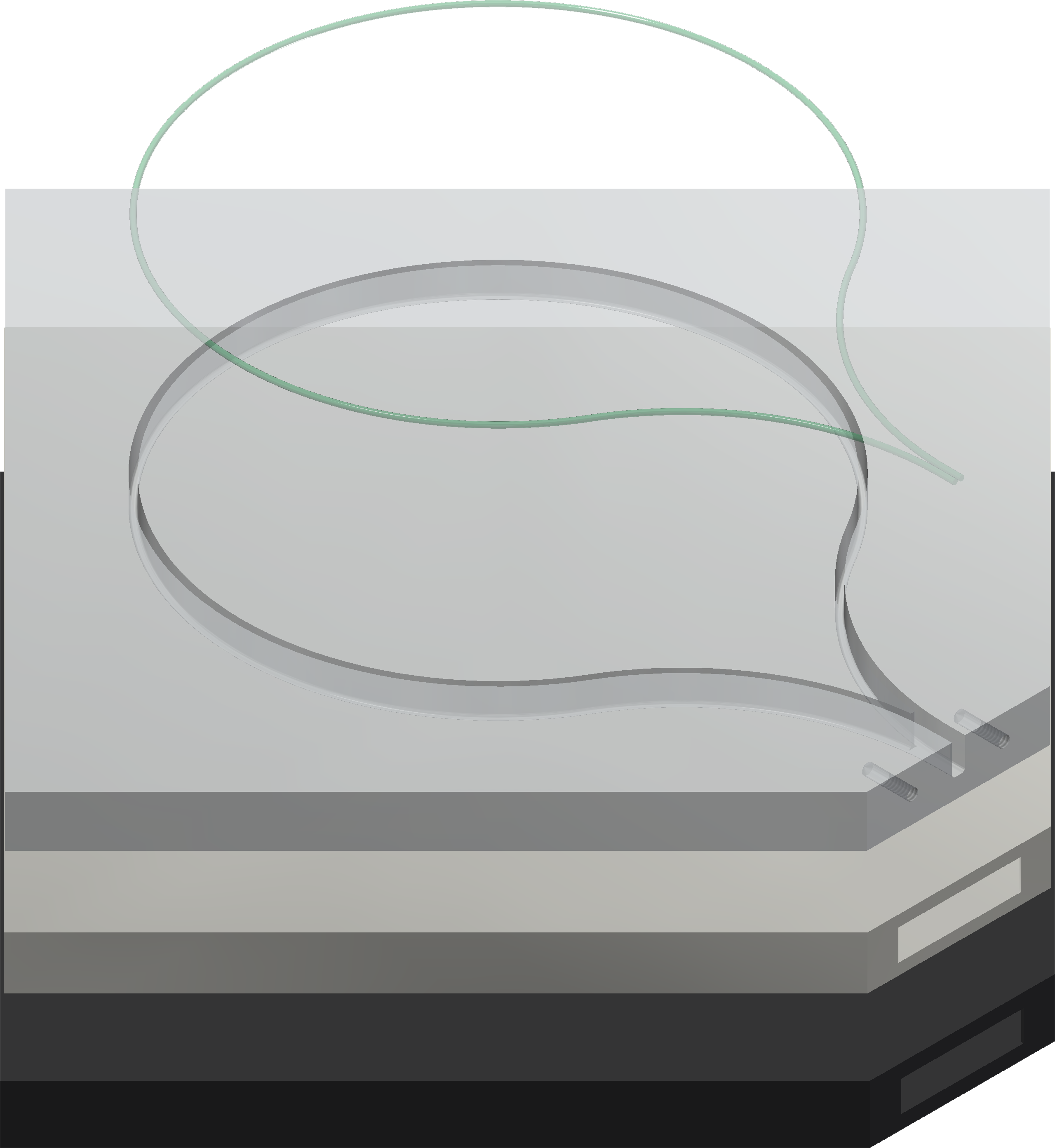
Milling
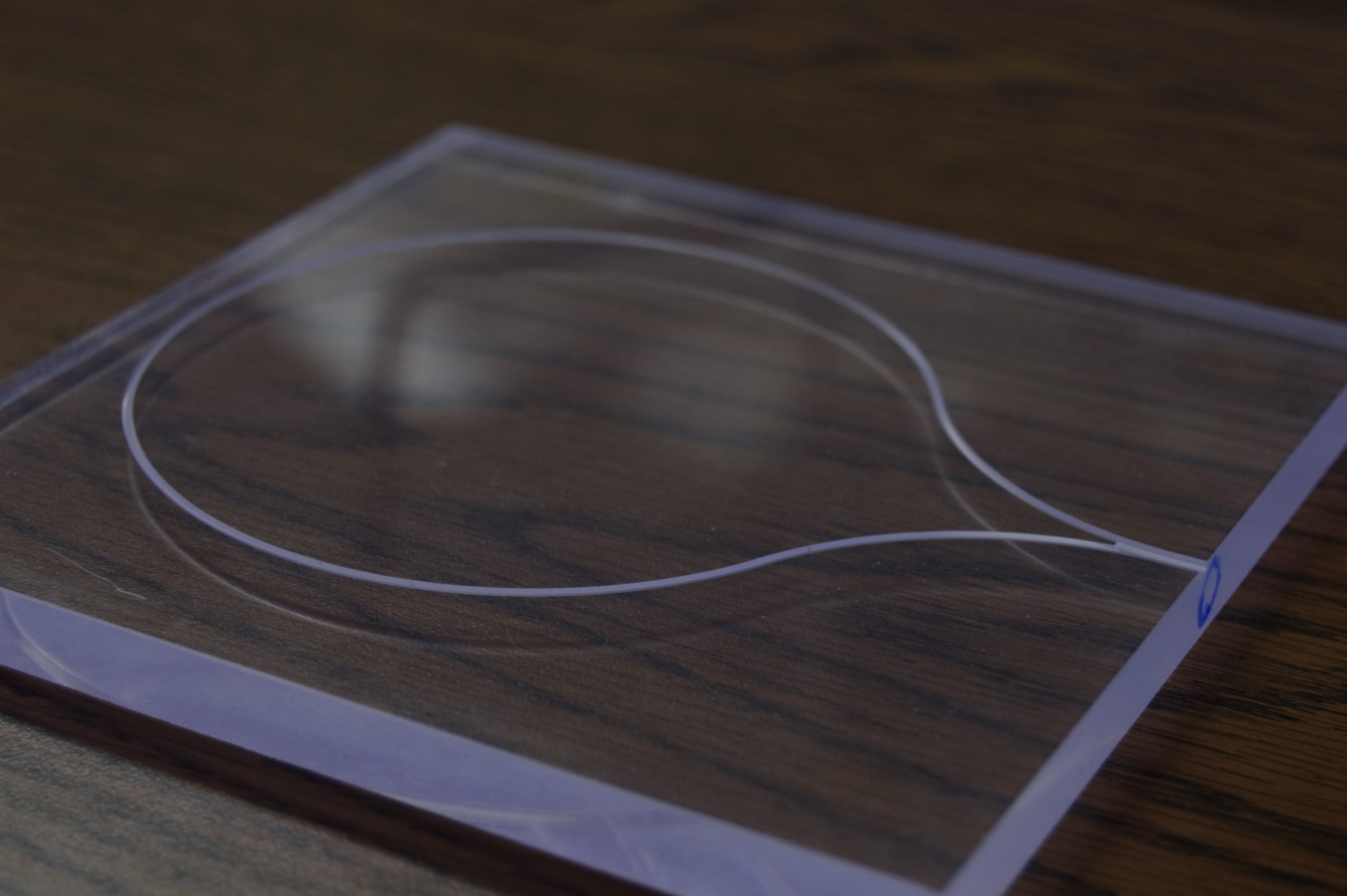 The tiles are received from the manufacturer and, with our machine shop at the GSU Physics and Astronomy department
milled into the dimensions needed, including a channel for the fiber that is installed later.
[Machine drawings details]
The channel is milled with a 1.3mm ball mill to provide clearance. In these designs the fiber is installed close to the
surface and then brought down to the center of the tile to keep as much scintillating material as possible in the
particle path. The edge has a chamfer and holes drilled and tapped for mounting. We have gone through multiple mounting
configurations with sensor designs, but this is a good example.
The tiles are received from the manufacturer and, with our machine shop at the GSU Physics and Astronomy department
milled into the dimensions needed, including a channel for the fiber that is installed later.
[Machine drawings details]
The channel is milled with a 1.3mm ball mill to provide clearance. In these designs the fiber is installed close to the
surface and then brought down to the center of the tile to keep as much scintillating material as possible in the
particle path. The edge has a chamfer and holes drilled and tapped for mounting. We have gone through multiple mounting
configurations with sensor designs, but this is a good example.
Polishing
[Example scintillator with polished and unpolished surfaces]
The panels from the milling procedure are then polished. Although the cutting surface is smooth it is not optically
clear. The sides being optically clear provides a higher efficiency though more internal reflection. There are multiple
polishing techniques and Ben Krasnow of Applied Science has a wonderful comparison of vapor, abrasive, and heat
polishing linked in the recommended reading.
[Polishing pictures]
We use Novus polishing compound on all the flat surfaces yielding crystal clear sides.
Gluing Fiber
[Pictures of gluing fiber]
The fiber is glued into channel with optical cement [Note cement we used], this provides optical filling making the
milled section boundary clear and provides an optical path to the fiber and holds it in place. After the epoxy cures,
the fibers are fly cut flush with the surface and polished to optical clarity again to maximize light yield.
Coatings
[Pictures aluminum foil and tape coatings]
At this point the tiles are complete, but two coatings need to be added to increase efficiency and make them useable. In
this state, ambient light, will be much greater than any signal so the tile needs to be shielded. The method used for
these tiles is firstly they are wrapped in washed household aluminum foil with the more reflective side facing inwards.
The foil is milled in two layers, and the dull side is in contact with more foil, and it should be washed with a
detergent since oil residue is left on the surface from the milling rollers. This provides a surface to reflect any
additional light back into the tile.
[Example finger scintillator]
This is then covered with a layer of black vinyl electrical tape. This provides the final layer of shielding from
external light. When the sensor is attached extra tape can be added to cover the interface area.
[Reflective spray and plasti-dip finger]
We have also investigated the feasibility of other methods of coverings. This is an example of a scintillator with a
fiber that is coated with a few layers of Spastix reflective spray paint and then dipped in Plasti-dip, a black
rubberized coating that can be applied though spray or immersion. A black spray paint could also be tested providing a
very thin coating for higher density.
[Spheinx inner HCAL tile]
Another item that provides excellent opaqueness for light blocking is Tedlar, a black polyvinyl fluoride film. A single
layer of the 1-2mil sheet provides complete opacity. It is also available with a single side with pressure sensitive
adhesive making application easy. This is highly recommended for future applications.
Conclusion
 The tiles, since they are just a plastic blend can be made in many shapes though injection molding, extrusion, or any of
the many existing methods avalible to the plastics industry to tune for light output, or detection area. We have these
panels made in the form that was most suitable for us, but the fundementals and processes can be scaled or changed to
make tiles for any exprement.
The tiles, since they are just a plastic blend can be made in many shapes though injection molding, extrusion, or any of
the many existing methods avalible to the plastics industry to tune for light output, or detection area. We have these
panels made in the form that was most suitable for us, but the fundementals and processes can be scaled or changed to
make tiles for any exprement.
Recommended reading
- Optical Finsh - Applied Science
- sPHENIX tile test Fermilab
- Fluorescence Spectroscopy
- Reflective spray comparison - Wayne Schmidt
- Flat black spray paint - Wayne Schmidt
- Kuraray Datasheet
- EJ-200 Datasheet
 Source: Wikimedia Commons
 Source: Edinburgh Instruments

 Unlike what we would expect from a single band emission, the emission is a spectrum. This is caused by there being many
vibrational and for each multiple rotational band. This yields an output where the individual bands are so numerous it
is not possible to resolve each transition and the output is a spectrum.
Unlike what we would expect from a single band emission, the emission is a spectrum. This is caused by there being many
vibrational and for each multiple rotational band. This yields an output where the individual bands are so numerous it
is not possible to resolve each transition and the output is a spectrum.
 Wavelength shifting fibers are plastic scintillators material formed into fibers and have a cladding similar to fiber
optic for light trapping and guiding.
[Kuraray Y-11 Datasheet]
Kuraray Y-11 is a 1mm blue to green wavelength shifting fiber and has a polystyrene core and a PMAA
(Polymethylmethacrylate) cladding of a single layer.
Wavelength shifting fibers are plastic scintillators material formed into fibers and have a cladding similar to fiber
optic for light trapping and guiding.
[Kuraray Y-11 Datasheet]
Kuraray Y-11 is a 1mm blue to green wavelength shifting fiber and has a polystyrene core and a PMAA
(Polymethylmethacrylate) cladding of a single layer.
 The tiles are received from the manufacturer and, with our machine shop at the GSU Physics and Astronomy department
milled into the dimensions needed, including a channel for the fiber that is installed later.
[Machine drawings details]
The channel is milled with a 1.3mm ball mill to provide clearance. In these designs the fiber is installed close to the
surface and then brought down to the center of the tile to keep as much scintillating material as possible in the
particle path. The edge has a chamfer and holes drilled and tapped for mounting. We have gone through multiple mounting
configurations with sensor designs, but this is a good example.
The tiles are received from the manufacturer and, with our machine shop at the GSU Physics and Astronomy department
milled into the dimensions needed, including a channel for the fiber that is installed later.
[Machine drawings details]
The channel is milled with a 1.3mm ball mill to provide clearance. In these designs the fiber is installed close to the
surface and then brought down to the center of the tile to keep as much scintillating material as possible in the
particle path. The edge has a chamfer and holes drilled and tapped for mounting. We have gone through multiple mounting
configurations with sensor designs, but this is a good example.
 The tiles, since they are just a plastic blend can be made in many shapes though injection molding, extrusion, or any of
the many existing methods avalible to the plastics industry to tune for light output, or detection area. We have these
panels made in the form that was most suitable for us, but the fundementals and processes can be scaled or changed to
make tiles for any exprement.
The tiles, since they are just a plastic blend can be made in many shapes though injection molding, extrusion, or any of
the many existing methods avalible to the plastics industry to tune for light output, or detection area. We have these
panels made in the form that was most suitable for us, but the fundementals and processes can be scaled or changed to
make tiles for any exprement.